| Line 28: | Line 28: | ||
==Description== |
==Description== |
||
| + | |||
| − | to be added |
||
| + | ;Output Voltage |
||
| + | This circuit uses the two rectifiers and capacitors to boost and rectifies the AC input voltage to about 320V DC. R4 and R5 are relatively large, and limit the output current to a small amount. So when you attach the zener diode it creates a [[shunt]] circuit, and the output voltage is set by the zener diode. |
||
| + | |||
| + | ;Output Current |
||
| + | R4 and R5 are relatively large, and limit the output current to a small amount. |
||
| + | |||
| + | |||
| + | |||
| + | |||
| + | ;Discharging |
||
| + | 320V is a high voltage and can be dangerous. So its important to lower the voltage to a safe level before you touch the contacts. R2 is used to discharge the bottom capacitor, and R3 is used to quickly discharge the lower capacitor when power is switched off. R1 is used to discharge the top capacitor and the neon lamp discharges the top capacitor when its voltage is above 80V. So when the switches are turned off the bottom capacitor quickly discharges and the output voltage is almost instantly lowered to around 160V. The upper capacitor discharges more slowly. It takes about 2-3 seconds to lower to 80V and the lamp turns off, and it takes about 7 seconds to drop to 10 Volts. But when the lamp turns off its safe to touch, and add/remove the diode. |
||
==How to use== |
==How to use== |
||
Revision as of 00:45, 19 February 2010
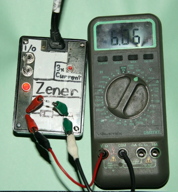
This is a circuit to test zener diodes. It hooks up to a 120V AC line and boosts the output voltage to over 300V allowing you to test zener diodes of any voltage. The circuit also has a push button switch to triple the current, if needed. The output is attached to 2 pairs of alligator clips. One pair is to attach to the diode. The second pair is to attach to a multimeter. The voltage across the diode is show on you multimeter.
Warning
It should be noted that this circuit could be dangerous. It is tied directly to an AC line, and has an output of 300V. The output has resistors on each line, which limits the current making it a bit safer, but will still give you quite a shock.
It should be switched off and light should be out while attaching and removing the zener diode
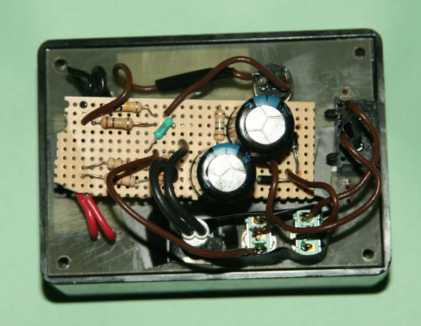
Components
- S1: DPDT switch, or 2x SPDT switches
- S2: Pushbutton switch
- N1: Neon lamp
- D1,D2: 1N4004, 1A 400V Rectifier
- C1,C2: Electrolytic Capacitor 100uF 200V
- R1: 33kΩ Resistor 1/2W
- R2: 2.7kΩ Resistor 1/4W
- R3: 1MΩ Resistor 1/4W
- R4: 27kΩ Resistor 1W, or 2x 48kΩ Resistor 1/2W in parallel.
- R5: 48kΩ Resistor 1W, or 2x 100kΩ Resistor 1/2W in parallel.
- 4x alligator clips
Circuit

Description
- Output Voltage
This circuit uses the two rectifiers and capacitors to boost and rectifies the AC input voltage to about 320V DC. R4 and R5 are relatively large, and limit the output current to a small amount. So when you attach the zener diode it creates a shunt circuit, and the output voltage is set by the zener diode.
- Output Current
R4 and R5 are relatively large, and limit the output current to a small amount.
- Discharging
320V is a high voltage and can be dangerous. So its important to lower the voltage to a safe level before you touch the contacts. R2 is used to discharge the bottom capacitor, and R3 is used to quickly discharge the lower capacitor when power is switched off. R1 is used to discharge the top capacitor and the neon lamp discharges the top capacitor when its voltage is above 80V. So when the switches are turned off the bottom capacitor quickly discharges and the output voltage is almost instantly lowered to around 160V. The upper capacitor discharges more slowly. It takes about 2-3 seconds to lower to 80V and the lamp turns off, and it takes about 7 seconds to drop to 10 Volts. But when the lamp turns off its safe to touch, and add/remove the diode.
How to use

- Testing a zener diode
- Turn off the power, make sure the light is out
- Attach the multimeter, positive to positive (red), negative to negative (green)
- Set multimeter to DC voltage, at the range you expect the diode to be
- Attach the zener diode, positive to positive (red), negative to negative (green)
- Turn on the tester
- Read the output on the multimeter, and that's the zener diodes reverse voltage
- If the voltage is less than 1V you probably have diode hooked up backwards, or its not a zener diode
- If the voltage is not relatively constant, the zener diode is bad, or its not a zener diode
- If you need to test it with more current, press the button, and the current will be tripled.
- If you are testing high voltage zener diodes , you will probably need to use this
- If you are testing lower voltage zener diodes, the voltage should only change a little.
- Zener current verses zener voltage
- Normal current mode: Iz = (320 - Vz) / (R4 + R5)
- Triple current mode: Iz = (320 - Vz) / (R4)
- Remove the diode
- Turn off the power
- Wait until the light turns off
- Remove the diode